PCB Test
 PCB Flying Probe Test PCB Flying Probe Test
High fault coverage with accuracy in a short time
By using electro-mechanical controlled probes to access components on a PCB assembly, the flying probe delivers accurate tests in the shortest times.
Flying Probe pcb testing provides high fault coverage with accuracy and repeatability. There's no requirement for a test fixture.
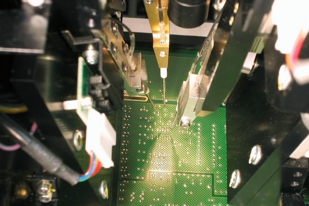
Probe precession can access various assembled components such as PLCCs, SOICs, PGAs, SSOPs, QFPs and others on PCB assemblies.
PCB Flying Probe Tests are ideal for:
• PCB Production ramp-up
• PCB Prototype test
• PCB Sample board test
• Large boards
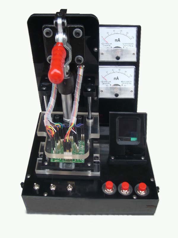
PCB Testing Jig
For mass production, in order to save cost and time, we will make the test Jig.
PCBA Test
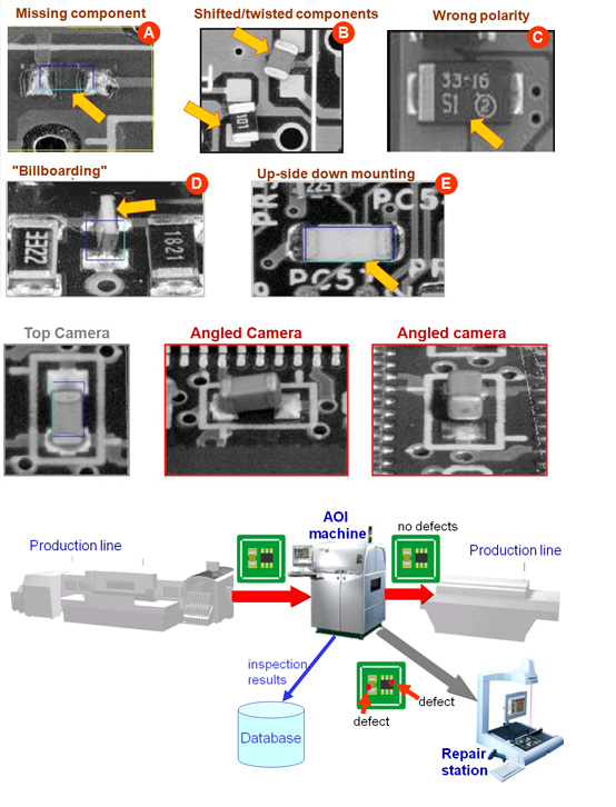
PCB AOI Testing
Automated Optical Inspection
Continuing miniaturization of components and increasing complexity of boards is driving the need for PCB AOI Testing:
Checks for missing components, offset, incorrect parts, polarity
Checks solder paste
Checks components down to 0603mm (0201")
PCB Parts Inspection
PCB Parts inspection is a computerized function that compares the image of a PCB captured by a CCD camera with the image of a good PCB memorized in advance, and determines whether it passes inspection or not.
This determination is performed at high speed by the specification of the portion to be inspected, the inspection of the existence of parts, positional divergence of parts, wrong parts, etc. As color factors are also inspected, objects which cannot be discriminated between good and defective by brightness alone can still be judged reliably.
PCB Solder Print Inspection
PCB Solder print inspection is a function that inspects the status of a solder printed surface by examining its area, place and form. Data processing is carried out in natural light, as in the previous parts inspection. Moreover, no special hardware is required.
The reference data for the solder printed surface to be inspected may be GERBER data, automatic sampling, or a manual designation.
PCB Solder Fillets Inspection
The M22X fw is equipped with a red LED for solder fillet inspection. The LED lights only during fillet inspection and emphasizes an inclined fillet; recognizing it clearly.
A captured image is processed by high-speed rendering. After the process, only the fillet parts are extracted from the image and judged to be good or defective.
PCB X-Ray Testing
We offer high-resolution PCB x-ray inspection of: BGAs, Micro BGAs, Chip scale packages, Large board capability is also suitable for inspection of bare boards
Faults Inspected
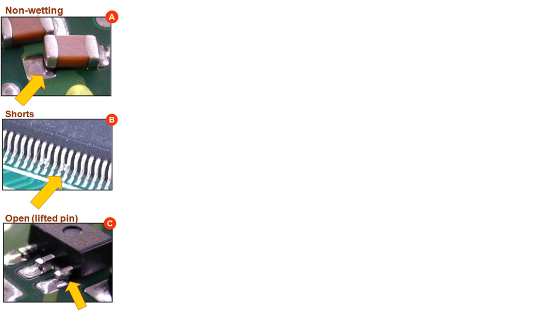
OPENS
Opens are usually caused by insufficient reflow, missing balls, doming, pop corning or contaminated board surface conditions.
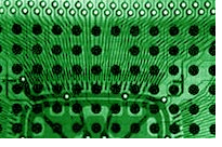
SHORTS
Shorts are easily found using X-ray.
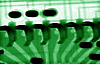
INSUFFICIENT REFLOW
Insufficient reflow is usually a little more difficult to spot. Some of the characteristics of a solder joint, which has not reflowed properly, include rough grainy appearances on the edges of the solder joint and an irregular shape of the joint.
DOMING
Doming is a defect common when a package has not been stored in nitrogen or other types of non-humidity chambers. The characteristics of the doming effect are the center solder joints of the BGA are slightly smaller than those on the outside edge.
POTATO CHIPPING
Potato chipping occurs when a component's outside edge lifts up from a pad. This will cause the center joints to appear squashed as a result of overheating the component.
VOIDS
Voids are usually found on boards which have not been through reflow long enough. They are typically created by flux gases that are unable to escape.

Functional Test: A Final Manufacturing Step
Functional test (FCT) is used as a final manufacturing step. It provides a pass/fail determination on finished PCBs before they are shipped. An FCT’s purpose in manufacturing is to validate that product hardware is free of defects that could, otherwise, adversely affect the product’s correct functioning in a system application.
In short, FCT verifies a PCB’s functionality and its behavior. It is important to emphasize that the requirements of a functional test, its development, and procedures vary widely from PCB to PCB and system to system.
Functional testers typically interface to the PCB under test via its edge connector or a test-probe point. This testing simulates the final electrical environment in which the PCB will be used.
The most common form of functional test, known as “hot mock-up” simply verifies that the PCB is functioning properly. More sophisticated functional tests involve cycling the PCB through an exhaustive range of operational tests.
Customer Advantages of Functional Test:
a) Functional test simulates the operating environment for the product under test thereby minimizing the expensive cost for the customer to provide the actual testing equipment
b) It eliminates the need for expensive system tests in some cases, which saves the OEM lots of time and financial resources.
c) It can check the functionality of the product anywhere from 50% to 100% of the product being shipped thereby minimizing the time and effort on the OEM to check and debug it.
d) Prudent testing engineers can extract the most productivity out of functional test thereby making it the most effective tool short of system test.
e) Functional test enhances the other types of tests such as ICT and flying probe test, making the product more robust and error free.
A functional test emulates or simulates a product’s operational environment to check its correct functionality. The environment consists of any device that communicates with the device under test (DUT), for example, the DUT’s power supply or program loads necessary to make the DUT work properly.
The PCB is subjected to a sequence of signals and power supplies. Responses are monitored at specific points to ensure functionality is correct. The test is usually performed according to the OEM test engineer, who defines the specifications and test procedures. This test is best at detecting wrong component values, functional failures and parametric failures.
Test software, sometimes called firmware, allows production line operators to perform functional test in an automatic way through a computer. To do this, the software communicates with external programmable instruments as a digital multi-meter, I/O boards, communication ports. The software combined with the fixture interfacing the instruments with the DUT make it possible to perform a FCT.
|